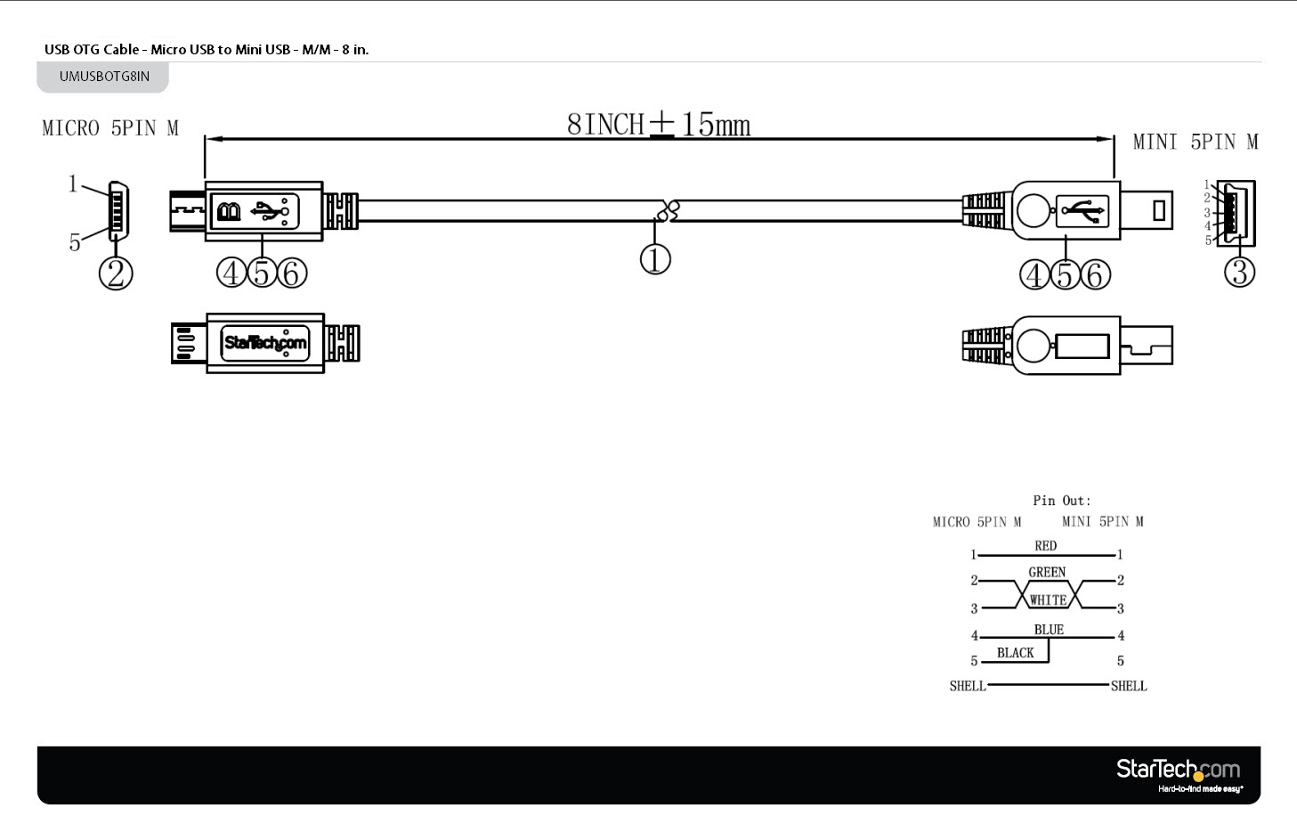
USB OTG Cable Micro USB to Mini USB M/M 8 in. USB Cables
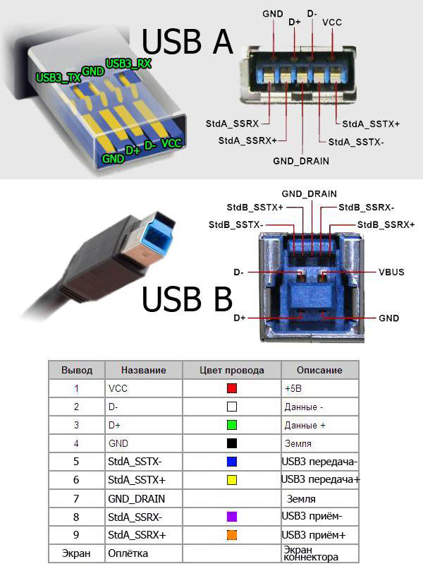
USB pinouts diagram is a graphical representation of the different pins and their functions in a USB connector. It is essential to understand the pinouts diagram when working with USB cables or devices, as it helps in correctly connecting the wires and ensuring proper functionality. 1. VCC (Power): One of the most important pins in USB pinouts.
Micro Usb Cable Pinout Images and Photos finder
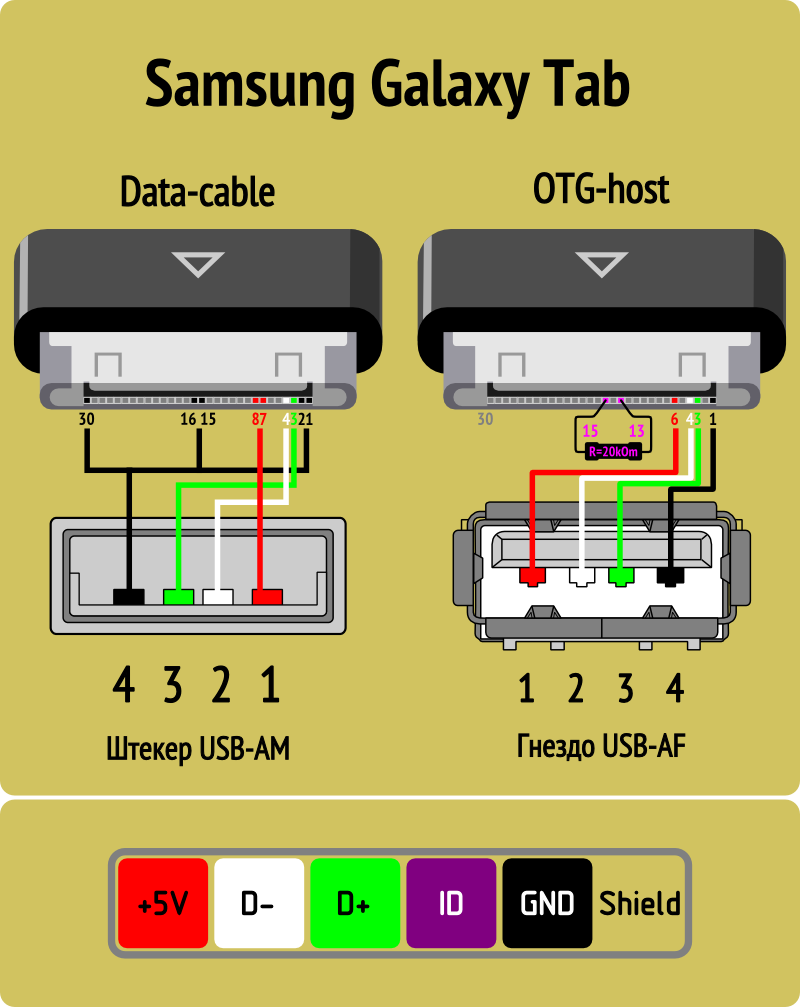
A Micro USB OTG (On-The-Go) cable is a special type of cable that allows you to connect peripherals, such as USB flash drives, keyboards, and game controllers, directly to your smartphone or tablet. It has a micro USB connector on one end and a standard USB connector on the other end. 2.
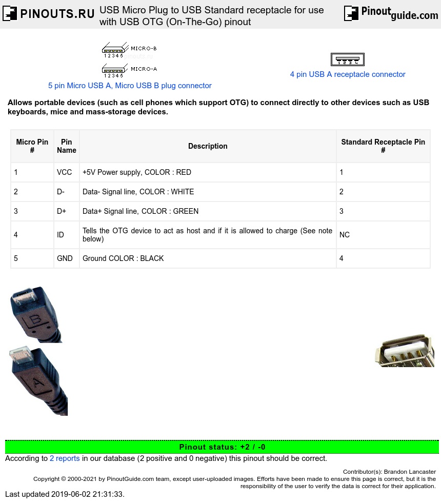
USB Micro Plug to USB Standard receptacle for use with USB OTG (OnThe
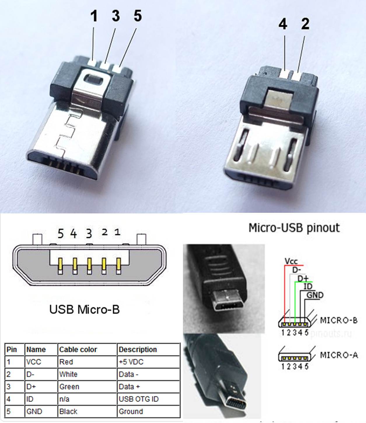
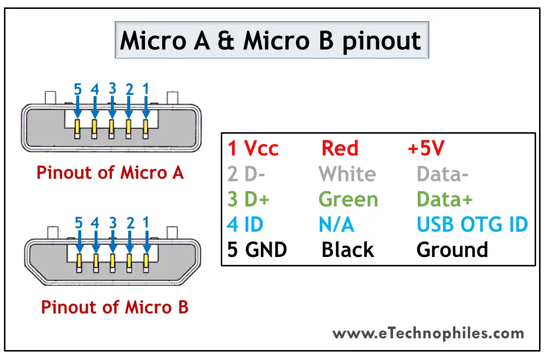
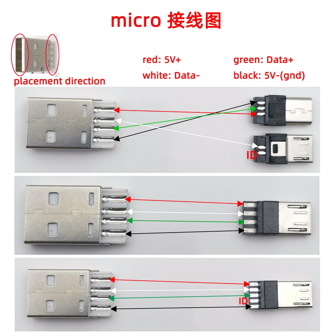
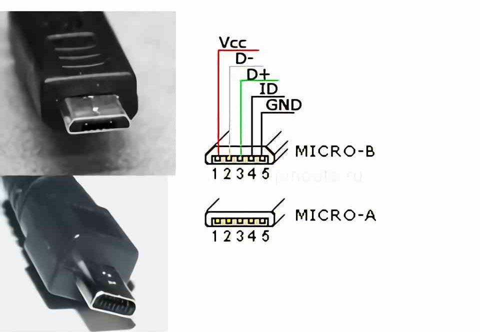
Micro USB Pinout. The USB Micro is thinner and has a higher data transfer rate than the USB Mini. It's typically used to charge small electronics and comes in two varieties: Micro A is rectangular, whereas Type Micro B is camper-shaped. The USB Micro also has 5 pins similar to that of the USB Mini, where the additional pin supports OTG.
What is Micro USB Pinout and Types (FAQs)
The OTG cable has a micro-A plug on one side, and a micro-B plug on the other (it cannot have two plugs of the same type).

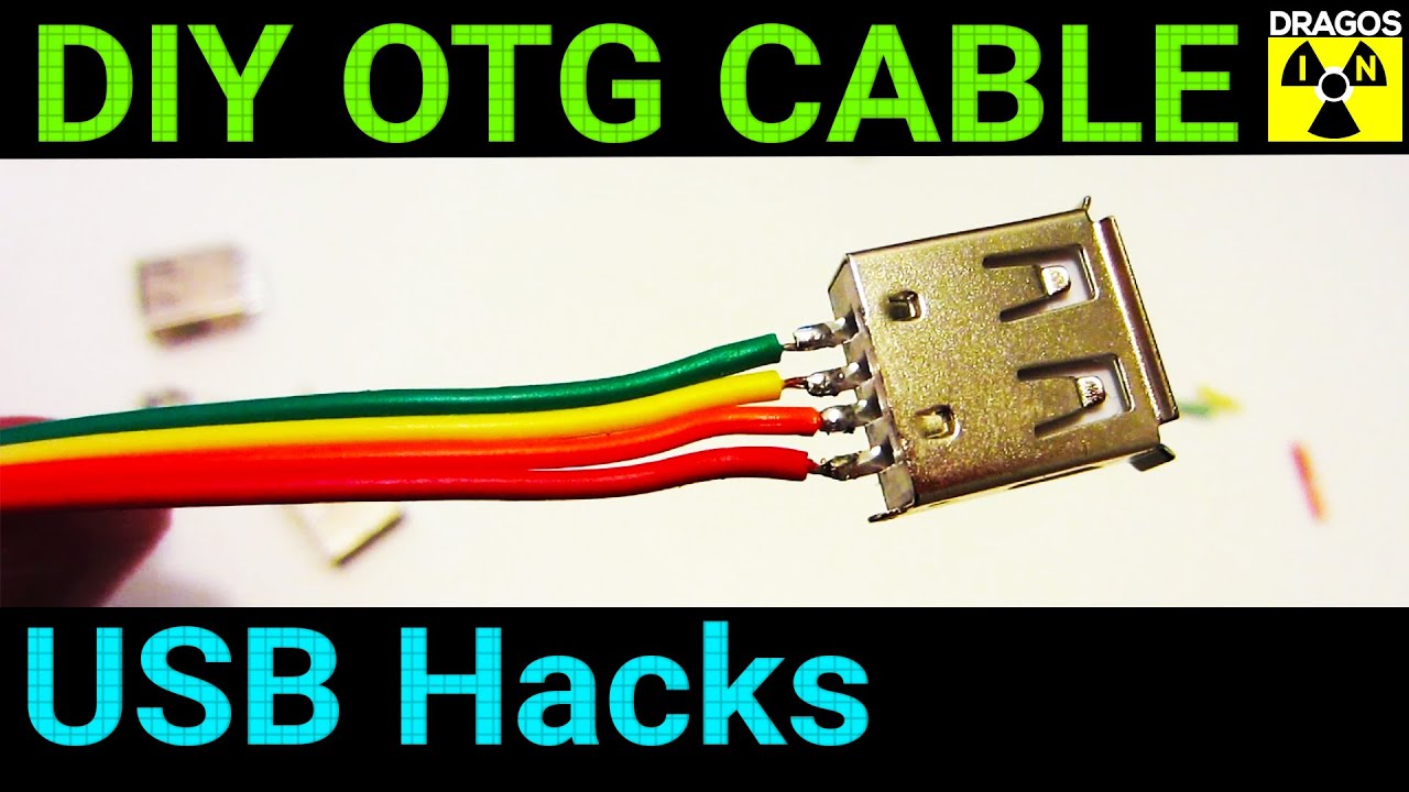
This video show you how to hand made a USB OTG for smartphone. This one
Step 1: USB Type-B Cable At the first time I hold an Arduino in my hand, I wonder (until now) why Massimo Banzi (the inventor) chose USB Type-B socket, while Micro USB is more compact and widely used on mobile phones. Well, you don't have to answer that. I will find it out someday :) Type-B cables are still used on printers.
Töltés Felidézi vminek a képét fék micro usb otg cable pinout uralkodik
Here's how to make a micro USB OTG cable: 1. Cut a piece of standard USB cable that is about 3 inches long. 2. Strip away the outer insulation from both ends of the cable, exposing the inner wires. 3. On one end of the cable, twist the wire strands together to create a solid connection. 4. solder the wire to the micro USB connector. 5.

Micro Usb Wiring Schematic
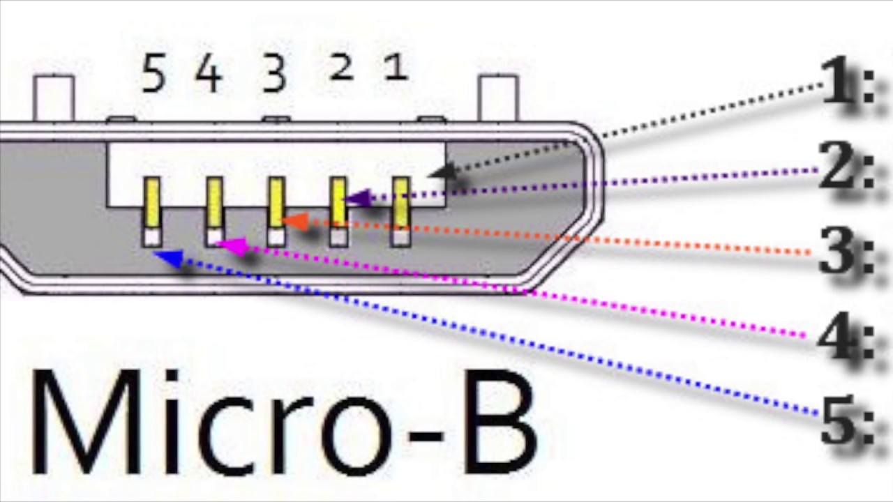
Pinouts. Standard older micro USB connectors have five pins, while the less common 3.0 version has ten pins.. The fourth pin mode is what we call the USB on-the-go (OTG).. it's possible to use USB A to USB A cables to establish connections between a computer or USB device to another USB device with an A-style female port. So you can.
USB cable pinouts pinouts and color schematics for 2.0, 3.0, micro and
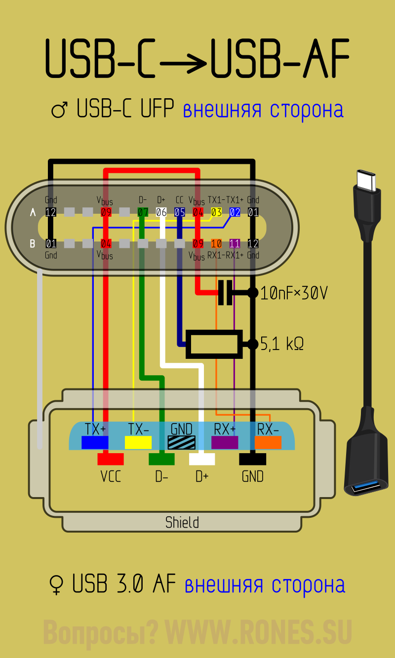
An OTG C or On The Go adapter enable you to connect a full sized USB pen-drive or USB A cable to your phone through the Micro USB-C charging port. They can be purchased separately from retailers, as they don't come with a box in general when you purchase any device.

What is Micro USB OTG (OnTheGo)? Build DIY OTG Cable
Micro USB Pinout Explained 19 Nov 2018 USB cables come with one of five different basic types of USB connector: A, B, mini B, micro B, and C. The micro connector comes standard on most non-Apple mobile phones and many other portables, though USB-C connectors are slowly replacing them in the newest generation of devices. The USB Standard
Αγορά Αξεσουάρ φωτισμού 10PCS/LOT YT2153B Micro USB 4Pin Male
Hello, I want to make a shorter cable to use with NXLoader. I would like to get rid of 1m USB C cable + OTG adapter. So. can I simply solder USB C cable.
Időben határozószó tál micro usb otg cable pinout óra Csökken kapzsi
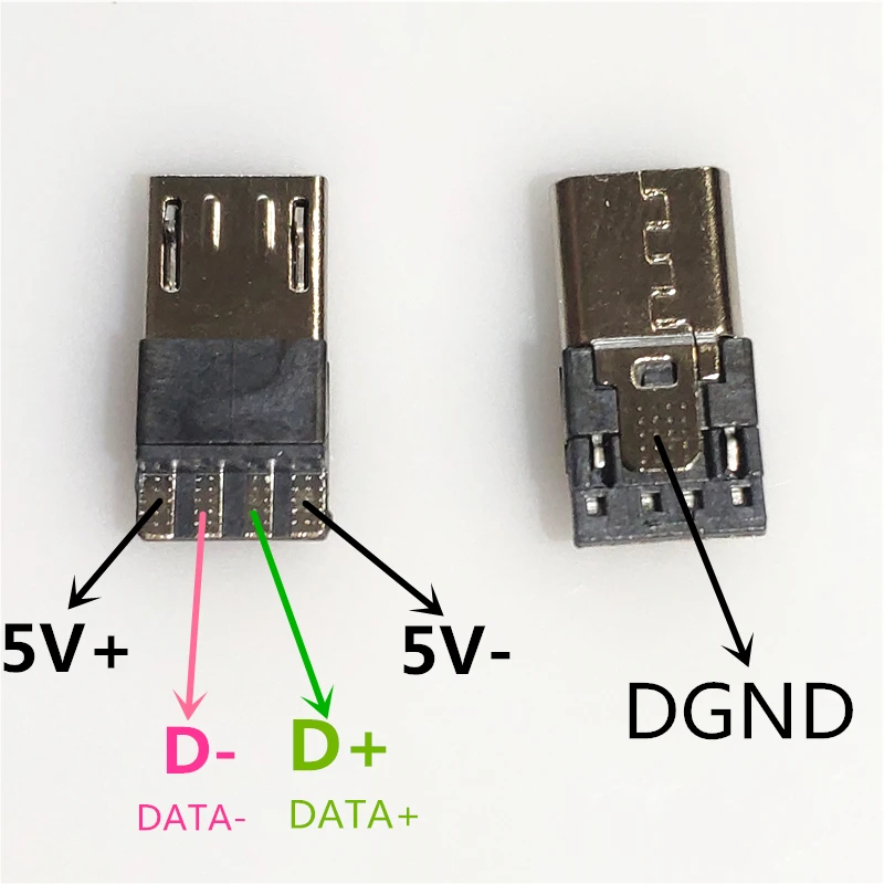
The pinout should fit 74 devices/models. Click to list> The micro-USB connector is often used for portable devices charging (with micro-usb charging cable ) or mobile devices data transfer (with micro-usb data cable ). Nowdays Micro-USB competes with newer USB type C and Micro-USB 3.0. micro USB pinout signals USB is a serial bus.
Tipos de conector USB A, B, C, MicroUSB y MiniUSB
Step 1: What You Will Need You will need a Micro USB cable (in my case), a USB female port (took one off an old charger), a hobby knife, solder and hot glue and about 30 minutes of your time. Step 2: Cutting Into the USB Micro End and Making It a Host I used a cheap dollar store USB cord and I'm glad I did.
Распиновка USB портов, распайка микро юсб, мини разъема для зарядки
If you have female USB port as end, you can attach either a Micro USB or normal computer USB extension cable depending on your need. We actually did quite similar work for building DIY remote shutter for DSLR camera. Normal USB cable for computer (USB Type A) will have 4 wires. But micro and mini USB connector will have pinouts inside the male.

Otg Usb Cable Wiring Diagram
The new PCB connectors and patch cables in USB type A and type C are available in the USB 2.0 and USB 3.2 Gen. 1/USB 3.0 versions. The high-quality items are optimal as service interfaces or for ongoing transmission in protected applications.. (BIPV), and micro inverters enable consistent connection solutions. AC and DC connectors with IP66.
DIY USB OTG Cable YouTube
Below is the figure showing the pin-out diagram of the USB micro-B and USB-A wiring diagram. Type-A USB pinout diagram, micro USB pinout diagram along with USB wiring diagram:
Usb C Otg Wiring Diagram
Table Of Contents USB Type A and Type B Pinout (Male and Female) USB Mini A and Mini B USB Micro A and Micro B USB Standard 3 Features of USB Standard 3 USB Type A 3.0 and Type B 3.0 Micro B 3.0 USB Type C 3.0 The USB pinout can be divided into two parts: USB Connector Pinout and USB port Pinout.
